


Ovidius Research Platform
Development of the research platform
The activities for the development of the platform started from concept design, which was conceived based on discussions with project partners, researchers from Ovidius University involved and other local researchers involved in studies of the Siutghiol lake, including water quality, societal impacts on the lake, flora and fauna, geography and geology. Based on these discussions, the concept of the platform needed to comply with the following requests:
- The platform should be large enough to withstand the yearly lake weather (wind, waves, corrosion)
- The platform should be large enough to support the loading of equipment and researchers and to allow the researchers to conduct experiments onboard
- The platform should be small enough to be towed into position by minimum two people, with the help of a small, motorized boat
- The platform should have its own power generation system and not to be dependent on shore power
- The platform should be modular, for deployment versatility
- The research equipment must be housed in weatherproof containers, onboard the platform
- The initial research equipment must comply with project activities, but the platform must be versatile enough to accommodate new equipment.
After many iterations and construction material analyses for existing floating platforms, the first concept design of the platform was generated based on the above-described requirements and limitations, which is presented in the figure below:
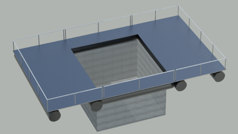
During the tendering procedures for platform manufacturing, the company which presented the offer, also proposed a technical design of the platform, together with materials and components. The design is presented in the figures below:
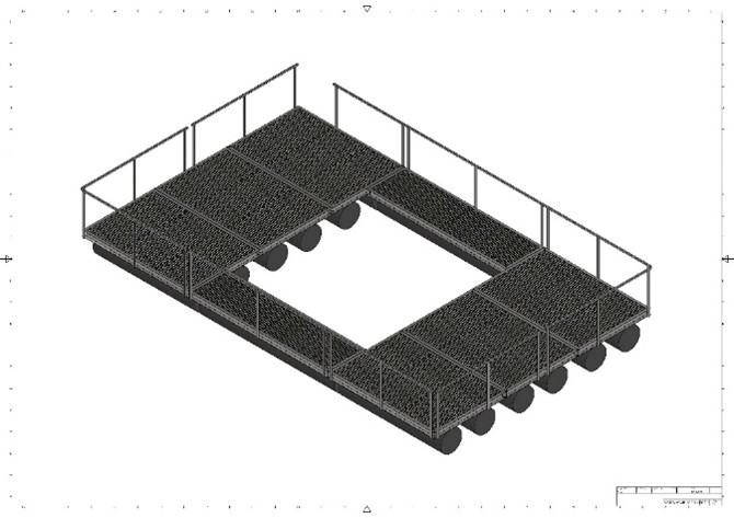
The proposed platform is approximately 10.5 meters long and 6.5 meters wide, with a 4 x 4 meters center area for long-term growth and research of fish species in open water conditions. In December 2025, the tender for the acquisition of the platform was completed.
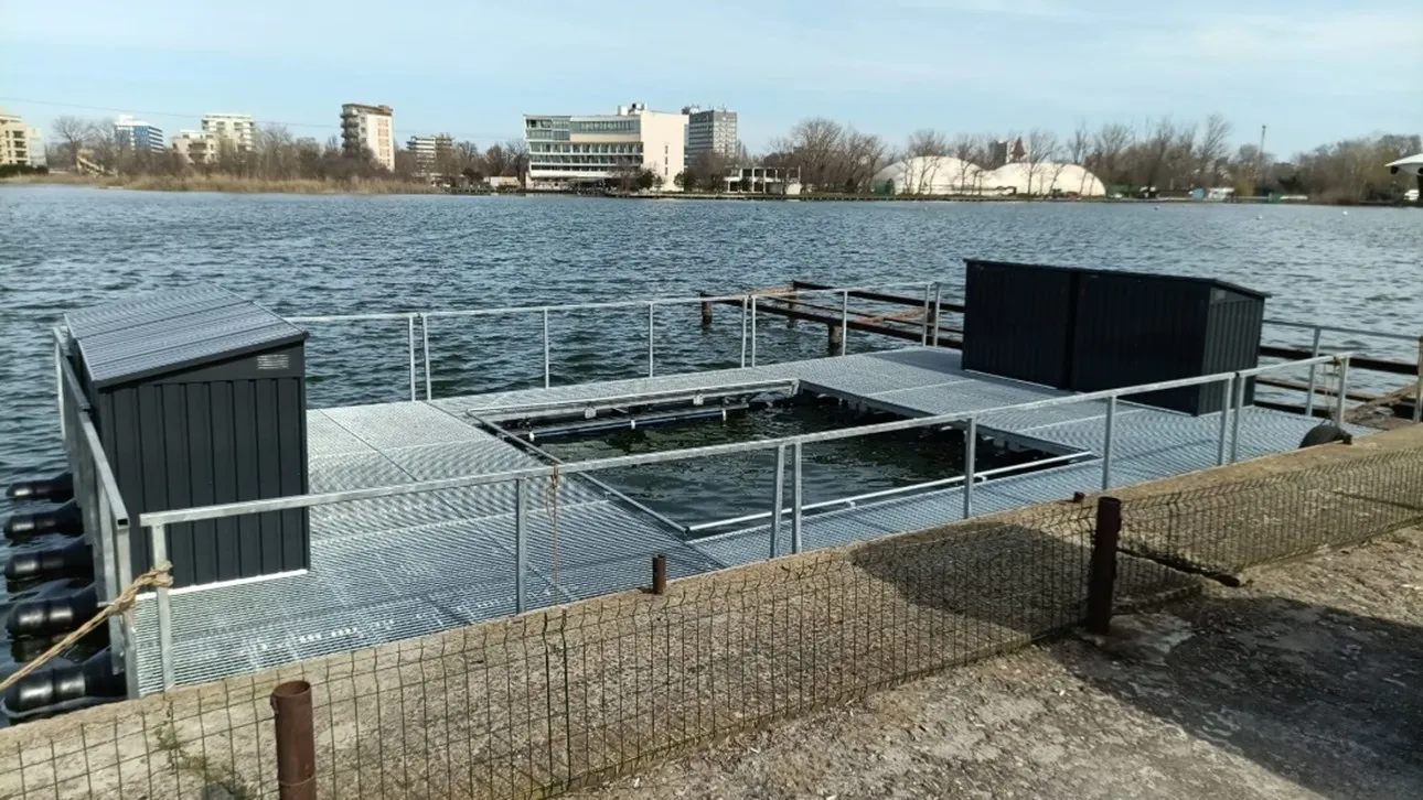
Platform deployment on Siutghiol lake
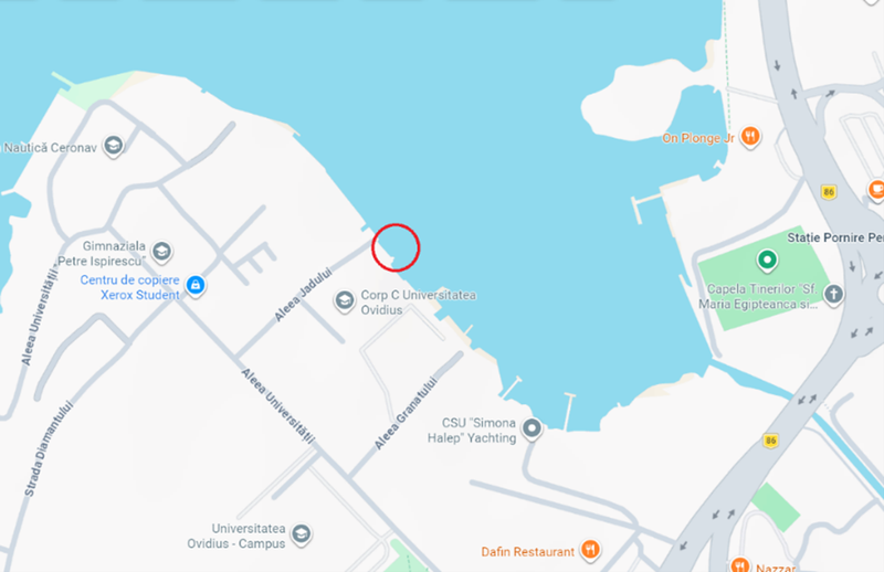
The location for the initial platform installation was chosen based on truck accessibility, available area for material discharging and the mooring possibility to shore. The location was close to the C Building of the Ovidius University Campus, which is also under permanent human and CCTV surveillance.
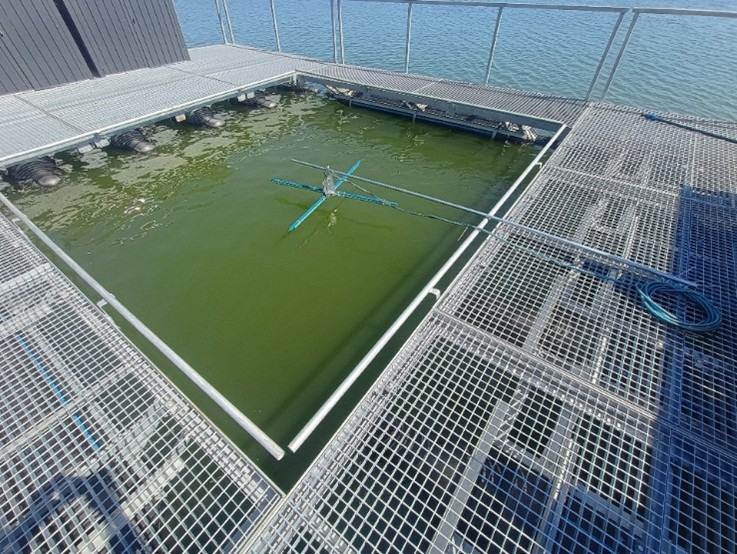
The platform was developed as modules and other small components, and it was assembled directly on the lake water.
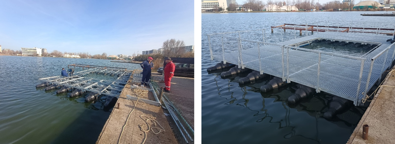
The floating elements of the platform were manufactured from high density polyethylene pipes. The superstructure of the platform was made from galvanized steel profiles. The final working area was covered with galvanized steel grates. This configuration allows a loading of approximately 4 tons for the entire platform. The connections between modules are done as a removable assembly, which allows the reconfiguration of the modules in other geometries or the deployment of separate modules in different locations.
On the platform, there were 4 weather-proof cabinets installed, for housing the onboard equipment.
The deployment location of the platform allowed the testing of stability in adverse weather conditions, as the area is exposed to the northern winds. The configuration of the lake allows high waves to be formed in the southern part of the lake, only when high velocity winds are blowing from north or north-north-west. During winter, the platform was deliberately exposed to unfavorable conditions, to test its stability, structural strength and mooring configurations.
Onboard support equipment of the platform
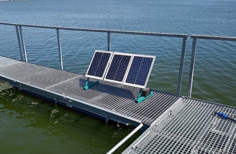
The next step was the installation of the photovoltaic system, for local energy generation. In the early concept design stage, the system was conceived for mounting laterally on one crossing of the platform, to lower the load and increase the flotation capacity of the platform.
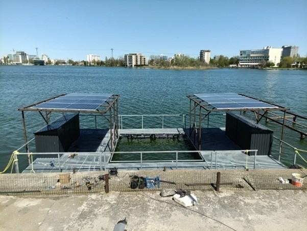
However, during the development works, it was considered that the dimensions of the solar panels would occupy a large working area of the platform. In this respect, it was decided to make the additional manufacturing of two supports for mounting the solar panels at a height of about 2 meters above the working area.
The configuration would decrease the floatability reserve of the platform, but it would provide two areas of shelter during rains or sunny days, as well as clearing the entire working area of the platform. The mounting of the solar panels was at a very small angle from the horizontal, as any increase in angle would increase the wind catching surface, would generate stability issues and impact structural integrity. The small angle allows the draining of rainwater from the surface of the solar panels.
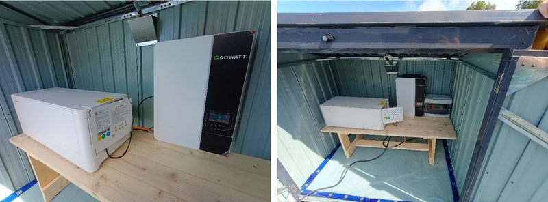
The solar PV system comprises of 8 x Canadian Solar 550W PV panels, Growatt SPF5000ES invertor with WiFi capability, 2 x Batteries Growatt ARK-2.5L-A1 LiFePo4 2.56kWh (Total 5,12kWh) and accessories for electric connections.
Another major support system is the water purification system. It consists of a combination of two separate filtration systems.
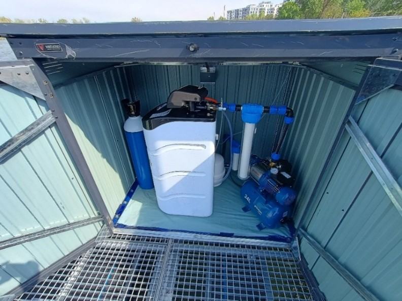
The first system is responsible for purifying the lake water, to a quality of less than 20 μS/cm. The second system is responsible for increasing the quality of the pure water to as low as 1 μS/cm, needed for laboratory experiments. The first system is a simple domestic filter, used to clean and purify the extracted ground water and make it usable for basic household activities. For drinking water, it uses a reverse osmosis filter to obtain pure water, which later is re-mineralized to potable water parameters.
In this case, it was necessary to obtain pure water. So, the remineralization and taste cartridges were bypassed. The circulation and required pressure of the water is achieved by a hydrophore, which passes the lake water through 2 mechanical filters, before feeding the clear water to the water softening system. After softening, normally the water would go to the house water network. However, here the necessity is to pass it through the reverse osmosis system. At the exit of the water softening system, the main water circuit is blinded, and the water is fed directly to the purification system.
As stated above, the first system is responsible for obtaining second grade pure water. The water enters the system, then goes through the sediment pp 5micron water filter cartridge which is stage 1 then through an activated carbon filter and then a carbon block filter. In this phase of filtration, the particles in suspension, the chlorine, its derivatives and other organic substances are retained. The water, after leaving the initial 3 filter filtration phase, is pushed towards the reverse osmosis membrane via the pump. The purified water is produced via this membrane and produces a minimum of 8 liters available in the pressure tank at any one time. A final rinse through an inline taste, odor and remineralization filter adds the final cleansing to ensure the highest quality and tasting water for you and your family to enjoy.
Research equipment of the platform
In the DTE Climate project description, there were identified the activities which will be carried out in order to reduce lake water eutrophication: hydrogen and oxygen production, injection of oxygen into the anoxic layers of Siutghiol lake and energy production from hydrogen as a backup of the photovoltaic system.
The tender for the acquisition of the platform included a water electrolyzer and a fuel cell.
Titan EZ-1500 stack
Titan series PEM Electrolyzer Stacks is an advanced patented product, which is lower voltage and higher efficiency, energy-saving and of environmental protection, producing hydrogen and oxygen through the electrolysis of pure water (without adding alkali).
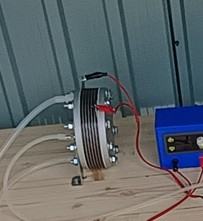
The proton exchange membrane (PEM) only allows water and positive ions to cross between compartments. The membrane also serves as the electrolyte in the cell, eliminating the need for hazardous liquid electrolytes such as concentrated potassium hydroxide. PEM water electrolysis simply splits pure deionized water (H2O) into its constituent parts, hydrogen (H2) and oxygen (O2), on either side of this membrane. When a DC voltage is applied to the electrolyzer, water fed to the anode, or oxygen electrode, is oxidized to oxygen and protons, while electrons are released. The protons (H+ ions) pass through the PEM to the cathode, or hydrogen electrode, where they meet electrons from the other side of the circuit and are reduced to hydrogen gas.
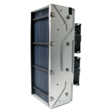
Fuel cell
The Horizon H-500 PEM Fuel Cell is a 500 Watt, air fed / air cooled, self-humidified hydrogen fuel cell. Because this fuel cell is air cooled there is no need for large, complicated, and expensive water cooling systems.
Horizon H-Series PEM fuel cells are semi-integrated, efficient, reliable systems that minimize the use of peripherals. As such, they are the most compact and lightweight fuel cells around the world.
The system includes:
- 1 x 500W fuel cell stack (includes supply valve, purge valve, blower)
- 1 x controller (includes short circuit unit) and this module is also known as electronic control box
- Connections and tubing
- Electronic valves
- Fuel cell ON/OFF switch
- SCU ON/OFF switch
Electrolyzer and fuel cell installation on the platform:
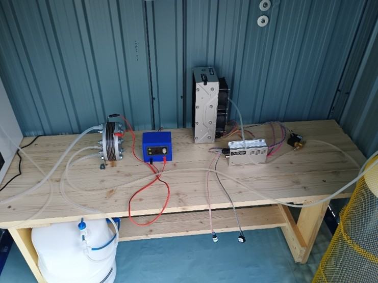
The water from the purification system is fed to the electrolyzer, which produces pure hydrogen and pure oxygen. The water is stored for use in a 10-liter tank. The produced hydrogen is stored in a 20-liter hydrogen tank, which can be pressurized up to 200 bar. However, for simplicity and safety reasons, the system relies on the output pressure of the electrolyzer, which can go as high as 10 bar.
From the hydrogen bottle, the gas is fed to the fuel cell, on request. The oxygen for the fuel cell is extracted from Ambiental air. The oxygen produced by the electrolyzer is used for injection into the anoxic layers of the lake. If necessary, a second oxygen bottle can be used for storage. As the hydrogen bottle, the oxygen bottle is 20 liters, 200 bars. But the working pressure is kept to 10 bar, as the output of the electrolyzer.
Inhouse produced systems
Local water aeration
A specific activity implemented on the platform is the aeration of anoxic bottom layers of the lake. The lake is mostly 4-5 meters deep, with previously recorded maximum depths of 14.9 meters and 9.65 meters at two locations of the lake. The two maximum depths are thought to be produced by underwater natural springs.
The area of the springs should be of better quality, as ground filtered water is injected into the lake. However, at the moment the exact location of the springs is only known to locals by visible modification of water quality or water temperature during winter.
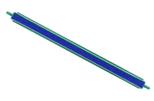
For the aeration of the anoxic layers of the lake, it was developed a simple system based on the so called “bubble bar”.
For the aeration system, 4 pieces of bubble bars were used, mounted on a stainless steel support. The distribution from the air hose was 3D printed and 6 mm hoses were used to connect all 4 bars.
The air is supplied by a normal air compressor. Because of the maximum depths (the measured depth at the location of the platform was 4 meters), the required pressure from the compressor is at maximum 0.5 bar. The compressor is a 24 liter, 8 bar, with a capacity of 160 liters per minute of air.
Water circulation for atmospheric aeration
Another implemented system is based on observation from nature. Natural aeration of water in fountains, often referred to as surface aeration, works by increasing the surface area of water that is exposed to the atmosphere, allowing oxygen to be transferred directly into the water. Fountains function by drawing water from the lower parts of a water body, usually with oxygen depletion and propelling it into the air, breaking it into small droplets before it splashes back down, which facilitates the exchange of gases, improves water quality, and helps to reduce odors and algae.
The implemented system onboard the floating platform is based on a submersible dirty water pump, to deliver the bottom water to a nozzle above the water.
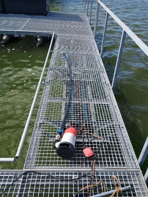
The pump can deliver 13500 liters per hour at a maximum height of 7 meters. When fitted with a 40 mm diameter pipe or hose, the pump can evacuate solid particles up to 35 mm.
In the current configuration, the pump was fitted with a 25 mm pipe, 3 meters long. The nozzle was 3D printed and installed about 50 cm above water.
The nozzle exit is variable and allows the modification of the flow, as required. It pulverizes the bottom anoxic water into air, which allows the absorption of gases. The system is in the early stages and in future configurations it will be developed as a floating small island for providing more airtime. Natural aeration of water over rocks is a vital ecological process where flowing water interacts with rocky surfaces to increase dissolved oxygen levels. As water cascades, splashes, and flows over rocks, it becomes turbulent, breaking the surface tension and mixing air into the water.
HHO Electrolizer
The open electrolyzer was developed in-house from stainless steel plates. The idea was to obtain a low cost device, to produce hydrogen and oxygen directly underwater.
The electrolizer consists of 28 plates, connected in pairs by stainless steel rods. The first tests were conducted in a small water tank, with dirty lake water.
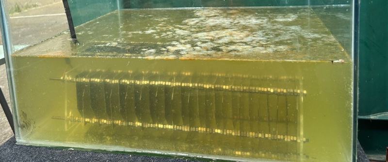
The initial tests showed a rapid flotation of suspended particles, while the necessary power to run the electrolizer was as low as 40 watt. The second test was made in lake water, from the platform. For this, it was implemented a direct PV to electrolysis system.
The first test was tried with direct power from the PV controller. The system is fitted with a small 12V 7 Ah solar battery and the output of the controller is 12 V at a maximum 10 Amps current. However, the controller does not have the capacity to inject current and the hydrolysis did not start.
In the second phase, a digital control module was used, with the capacity to provide up to 36 V and 5 A, at a maximum 80W power. The module has the capacity to convert the input power to any output voltage and amps, within the mentioned limits.
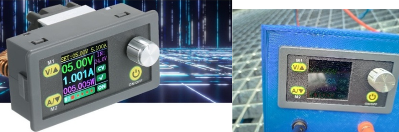
Due to the sunny conditions, it was difficult to take a picture of the display. The voltage was set to 12V and the amps were slowly increased up to 4. At 3 amps, the electrolyzer started to work, but at 4 amps, the bubbles were visible enough to be captured by the camera.